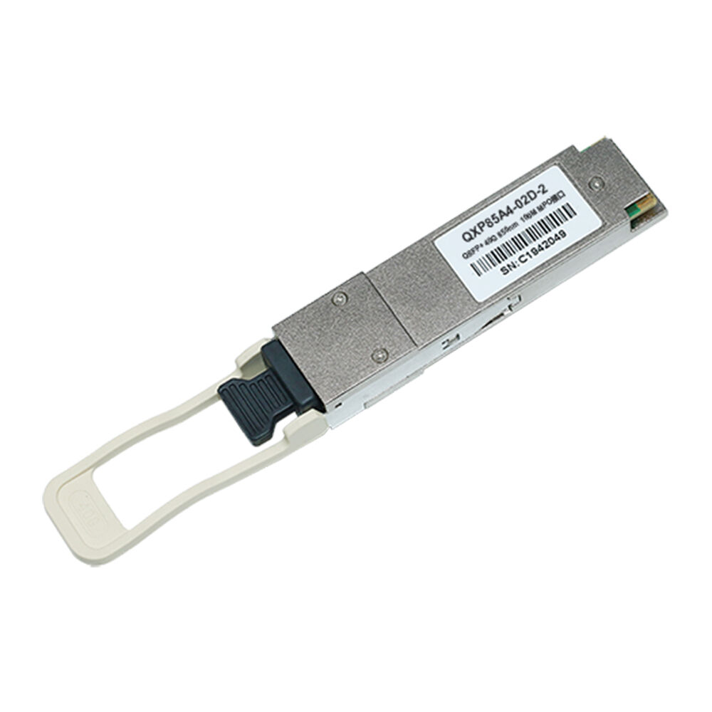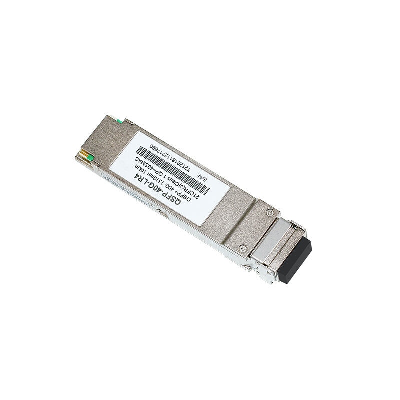
Home > Products > Optical Transceivers > 100G Optical Transceiver
Standards Compliant with 100G 4WDM-10 MSA Technical Spec Rev1.0 Complies with SFF-8661 Complies with SFF-8636 IEEE 802.3bm Annex 83E Interface
● Hot-pluggable QSFP28 form factor
● 4 CWDM lanes MUX/DEMUX design
● 4x25Gb/s electrical interface
● Supports 103.1Gb/s aggregate bit rate
● Up to 10km transmission on single mode fiber (SMF) with FEC
● LC duplex connector
● Operating case temperature: 0 to 70℃
● Single 3.3V power supply
● Maximum power consumption 3.5W
● RoHS compliant interference.
|
Parameter |
Symbol |
Min |
Typ |
Max |
Unit |
Notes |
|
Total Average Launch Power |
PT |
8.5 |
dBm |
|||
|
Transmit Average Power, each lane |
PAVG |
-6.5 |
2.5 |
dBm |
||
|
Optical Modulation Amplitude (OMA), each lane |
POMA |
-4.0 |
2.5 |
dBm |
1 |
|
|
Optical Extinction Ratio |
ER |
3.5 |
dB |
|||
|
Transmitter and Dispersion Penalty, each lane |
TDP |
3.0 |
dB |
|||
|
Launch power in OMA minus TDP, each lane |
-5.0 |
dBm |
||||
|
Side Mode Suppression Ratio |
SMSR |
30 |
dB |
|||
|
Average launch power of OFF transmitter, each lane |
Poff |
-30 |
dBm |
|||
|
Optical Return Loss Tolerance |
20 |
dB |
||||
|
Transmitter Reflectance |
-12 |
dB |
||||
|
Transmitter Eye Mask Definition {X1, X2, X3, Y1, Y2, Y3} |
{0.31, 0.4, 0.45, 0.34, 0.38,0.4} |
2 |
||||
|
Parameter |
Symbol |
Min |
Typ |
Max |
Unit |
Notes |
|
Receive Saturation (OMA), each lane |
Rmax |
2.5 |
dBm |
|||
|
Damage threshold, each lane |
THdmg |
3.5 |
dBm |
3 |
||
|
Average Receive Power, each lane |
-13 |
2.5 |
dBm |
|||
|
Unstressed Receiver Sensitivity (OMA) each lane |
SEN |
-11.5 |
dBm |
4 |
||
|
Stressed Receiver Sensitivity (OMA), each lane |
SRS |
-8.6 |
dBm |
5 |
||
|
Receiver Reflectance |
RR |
-26 |
dB |
|||
|
LOS Assert |
LOSA |
-30 |
dBm |
|||
|
LOS De-Assert |
LOSD |
-15 |
dBm |
|||
|
LOS Hysteresis |
LOSH |
0.5 |
dB |
|||
|
Conditions of Stress Receiver Sensitivity Test (Note 6) |
||||||
|
Vertical Eye Closure Penalty, each lane |
VECP |
2.6 |
dB |
|||
|
Stressed J2 Jitter, each lane |
J2 |
0.33 |
UI |
|||
|
Stressed J4 Jitter, each lane |
J4 |
0.48 |
UI |
|||
|
SRS eye mask definition {X1, X2, X3, Y1, Y2, Y3} |
{0.39, 0.5, 0.5, 0.39, 0.39, 0.4} |
|||||
1. Even if the TDP < 1.0 dB, the OMA (min)must exceed the minimum value.
2. Hit ratio of 5x10⁻⁵.
3. The receiver shall be able to tolerate,without damage, continuous exposure to an optical signal having this averagepower level.
4. For BER =5x10⁻⁵.
5. Measured with conformance test signal forBER = 5x10⁻⁵.
6. Vertical eye closure penalty, stressed eyeJ2 jitter, stressed eye J4 jitter, and SRS eye mask definition are testconditions for measuring stressed receiver sensitivity. They are notcharacteristics of the receiver.
• Data Center Interconnect
• 100G Ethernet
• 100G 4WDM-10 applications with FEC