Home > Products > Optical Network > OTN Transmission Platform
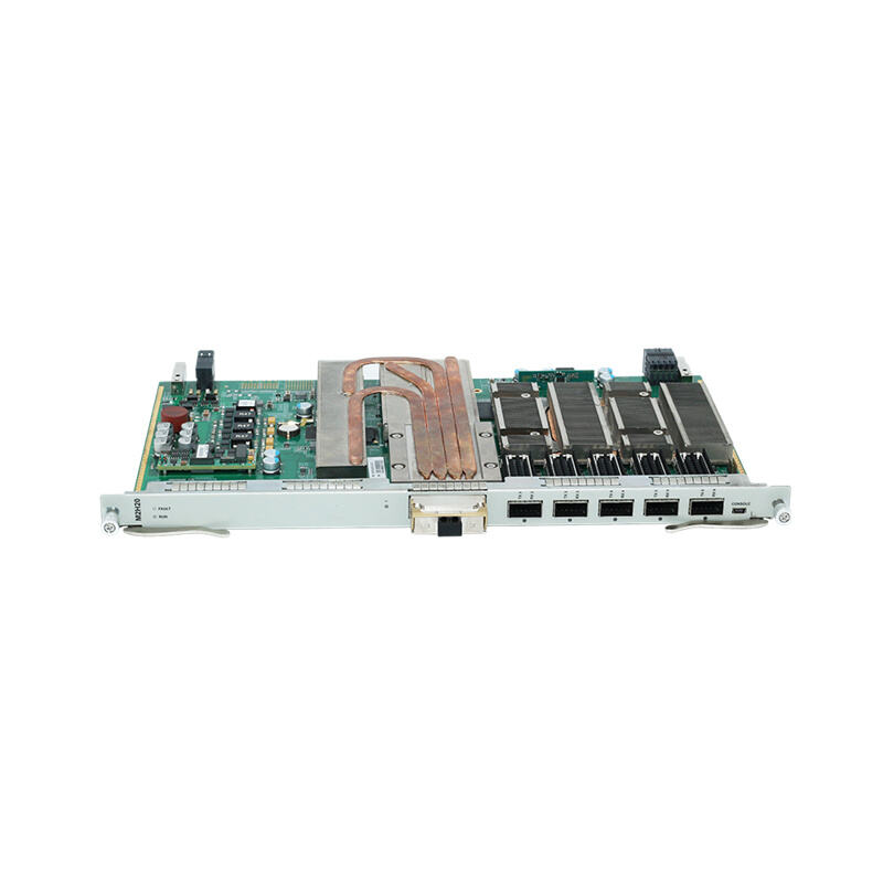
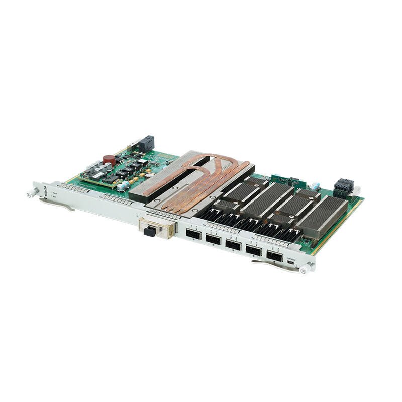
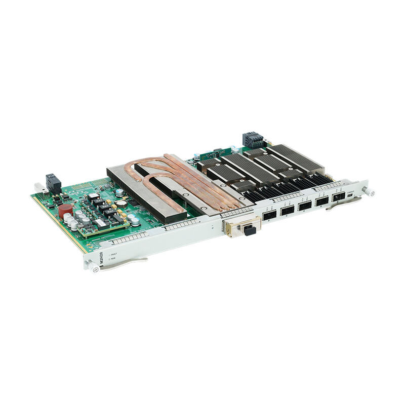
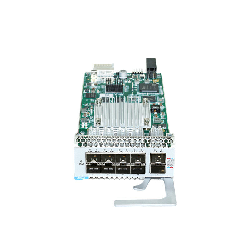
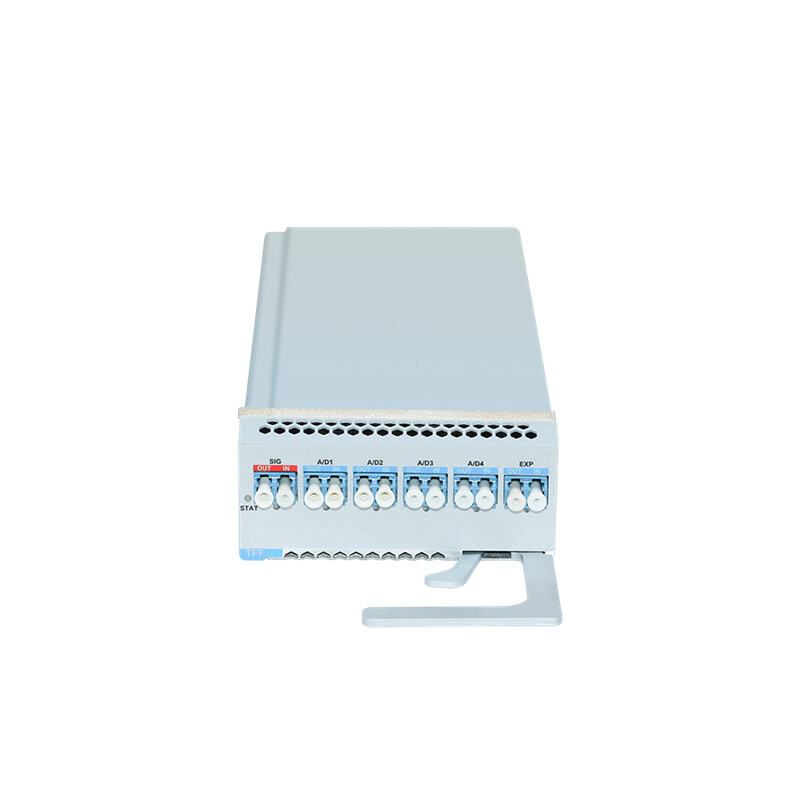
M2H20 is a 200G OTN Transponder/Muxponder board capable of packaging and de-packaging functions from 100G/40G/10G services to OTUC2. The client-side port allows access to 2 channels of 100G services, 4 channels of 40G services, or 20 channels of 10G services. Typical client services include 100GE, 40GE, and 10GE.
M2H20 is a 200G OTN Transponder/Muxponder board capable of packaging and de-packaging functions from 100G/40G/10G services to OTUC2. The client-side port allows access to 2 channels of 100G services, 4 channels of 40G services, or 20 channels of 10G services. Typical client services include 100GE, 40GE, and 10GE.
The line-side port supports either 1 channel of 200G OTUC2 signal or 1 channel of 100G OTU4 signal. It supports 8/16QAM modulation for 200G OTUC2 line mode, PM-QPSK modulation for 100G OTU4 line mode, as well as coherent modulation technology. The board also incorporates G.709 FEC and SD-FEC error correction functions to ensure reliable transmission.
|
Item |
M2H20 Description |
|
|
Indicator Light |
RUN |
Indicator Light of Board Running State. Slow Flash of Green Light: The system has been successfully started. Green Light Always OFF: The system has not been started. |
|
FAULT |
Indicator Light of Board Alarm. Quick Flash of Red Light: The board is mismatched. Slow Flash of Red Light: There is latchopen alarm of the board. Red Light Always ON: There is alarm of the board. Red Light Always OFF: There is no alarm of the board. |
|
|
Optical Interface |
1 |
Line-side optical interface, CFP2 packaging. |
|
2-3 |
Client-side optical interface, QSFP28/QSFP+ packaging. It supports access of 100G, 40G and 10G services. |
|
|
4-5 |
Client-side optical interface, QSFP+ packaing. It supports access of 40G and 10G services. |
|
|
6 |
Client-side optical interface, QSFP+ packaing. It supports access of 10G service. |
|
Item |
Description |
||
|
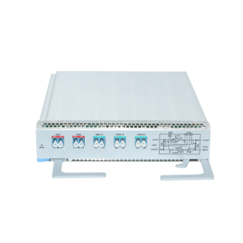
Client-side Optical Module |
M2H20 board provides 5 client-side optical transceiver moduels, which supports 2 channels of 100GE services access or 4 channels of 40GE services access, or 20 channels of 10G services access. Receiving Direction: Access 100GE, 40GE and 10G client services and realize optical-electrical conversion function of service signals. Transmitting Direction: Realize electrical-optical conversion and output 100GE, 40GE and 10G client service signals. |
||
|
ODUk Mapping Unit |
Realize the mapping/demapping process of client service electrical signals and ODUk (k=2, 2e, 3, 4) signals, and detect and process ODUk overhead. |
||
|
Service Cross-connect Unit |
Realize the cross-connect function of client service signals of the board, or the client service signals of other boards which are transmitted through the backplane bus. |
||
|
OTU Framing Unit |
Detect and process the overhead of OTUC2 or OTU4 frame, and complete the multiplexing/demultiplexing process of ODUk (k=2, 2e, 3, 4), OTUC2 (ODUC2) or OTU4 signals. |
||
|
Line- side Optical Module |
100G Mode |
M2H20 board provides 1 line-side optical transceiver module, which is pluggable packaing module (CFP2). When it is configured as 100G mode, it will realize optical-electrical conversion and electrical-optical conversion of OTU4 signals. Transmitting Direction: Access OTU4 electrical signals from OTU framing unit, and realize PM-QPSK modulation and FEC coding of signals, and then achieve electrical-optical conversion. After that, OTU4 optical signals are output. Receiving Direction: Realize optical-electrical conversion of OTU4 optical signals. Then achieve DSP processing and FEC error correction. After that, the signals are output to OTU framing unit. |
|
|
Line- side Optical Module |
200G Mode |
M2H20 board provides 1 line-side optical transceiver module, which is pluggable packaing module (CFP2). When it is configured as 200G mode, it can multiplex 2 channels of OTU4 signal to 1 channel of OTUC2 signal and realize optical- electrical conversion and electrical-optical conversion. Transmitting Direction: Access 2 channels of OTU4 electrical signals from OTU framing unit, and the signals are multiplexed to 1 channel of OTUC2 signal. Realize QAM modulation and FEC coding of signals, and then achieve electrical- optical conversion. After that, OTUC2 optical signals are output. Receiving Direction: Realize optical-electrical conversion of OTUC2 optical signals. Then achieve DSP processing and FEC error correction. After that, the signals are demultiplexed to 2 channels of OTUC4 signals which are output to OTU framin unit. |
|